Tag Archives: gearbox with

China Hydraulic Pto Cast Iron Gearbox Kmt7001 1: 3.5 with high quality

Merchandise Description

Hydraulic PTO cast iron gearbox KMT7001 1:3.5

The  Gearboxes are designed for connecting gear pumps to farm tractor power just take offs (PTO).Output pace of electrical power get offs is 540rpm which can be in contrast with the appropriate operating speeds of hydraulic pumps.Different enter operating speeds can also be ideal,supplied that the PTO gearbox output velocity does not exceed 3000 rpm.

Gears
Manufactured in Steel CZPT 18 PCR M03.Stub teeth assure very high resistance and run extremely quietly.

Shafts
Manufactured in steel CZPT sixteen CRN4.They are coupled with splined gears and are made to stand the torque values stated in the catalogue.

Lubrication
SAE ninety gear oil must be set in the pto gearbox prior to use, adjust the oil after the initial 60-80 hrs and then each twelve months or 1500 hrs which ever falls first.

Maintenance
Make sure you verify the oil level through the special oil window every fifty several hours.Operating temperatures should not exceed one hundred twenty levels celcius below continuos responsibility cycle.

Packaging & Shipping

Plastic bag packing for 1 piece / two pieces in 1 exporting carton / 100 cartons set on a pallet

FAQ


1.Q:Is your firm a trading company or a manufacturer?

A:Our company is a trading organization also a manufacturer, we have our own manufacturing unit to generate gearbox, pump help..Etc

Also we distribute gear pumps, tractor equipment,dump truck pump  from chosen quality suppliers to fulfill customers’ variable need.


two.Q:What about the good quality control and guarantee ?

A:”Quality 1st, Buyers foremost”.Each piece of goods is cheeked and examined strictly 1 by 1 before packing and shipping and delivery.

Our merchandise have 1 12 months warranty, specialized assistance is endless from us.


3.Q:Can you provide samples for checking and tests?

A:Indeed,we supply totally free samples for checking the build high quality and true functionality of our products,the freight want to be coverd by buyer.


4.Q:How can I get to your company?

A:Our business handle is No.888 Huaxu Road,Xihu (West Lake) Dis. district,ZheJiang ,China

It is about thirty minutes by car from ZheJiang Xihu (West Lake) Dis.ao airport or ZheJiang Xihu (West Lake) Dis.ao Railway station.

Type: Forest Machine
Usage: Agricultural Products Processing, Farmland Infrastructure
Material: Aluminum
Power Source: Diesel
Weight: 13kg
Transport Package: Carton+Pallet

###

Samples:
US$ 80/Piece
1 Piece(Min.Order)

|
Request Sample

###

Customization:
Available

|


Type: Forest Machine
Usage: Agricultural Products Processing, Farmland Infrastructure
Material: Aluminum
Power Source: Diesel
Weight: 13kg
Transport Package: Carton+Pallet

###

Samples:
US$ 80/Piece
1 Piece(Min.Order)

|
Request Sample

###

Customization:
Available

|


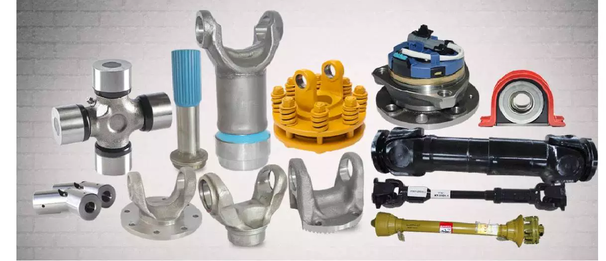
PTO Shaft Safety Chains

PTO shaft is the part of a tractor that helps transfer power from the tractor to the equipment it is hooked to. A PTO shaft is important if you have a tiller or bush hog. The correct PTO shaft size is crucial for both the tractor and the equipment. If the PTO shaft size is not correct for your equipment, it may not work.
>Shaft Collar

Safety chains

<br/Safety chains are an essential part of securing your PTO shaft. They prevent a rotating plastic shield from coming loose and causing injury or damage. It is important to protect your PTO and any other drive shafts on your machine. Watch the video below for more information about the dangers of unguarded PTOs.
PTOs are an efficient way to transfer mechanical power between tractors and implements. They helped revolutionize North American agriculture during the 1930s. Despite their convenience, PTOs have also proven to be one of the most common farm machinery hazards. This fact sheet outlines several important PTO safety precautions.
Safety chains for PTO shafts are necessary to protect both tractor and implement from damage. The PTO shaft must be attached properly to the tractor and the implement before starting the equipment. Before operating, be sure that the safety chains are positioned in a way that allows them to fully move. When operating the PTO, avoid being too aggressive as this can damage the drive line and shaft. For further safety, make sure to fit a torque limiter or clutch on the implement end of the PTO shaft.
PTOs are great for plowing, mowing, and shredding, but they also have potential to cause injuries if you don’t use a safety chain. It’s best to get a chain that is long enough to prevent injuries. Also, be sure that the PTO shaft does not compress completely at any point during the operating range. There should be several inches of overlap in the longest operating extension of the PTO.
Another common hazard with PTOs is IID shafts. While many machines and tractors have driveline guards, these are often missing. If you have a PTO with an IID, you should consider installing a safety chain.

Shield

A swingable tractor PTO shaft shield assembly consists of an inverted U-shaped shield member slidably attached to a bracket. It extends above the PTO shaft and has several notches and pins that engage each other. It can be held in a number of positions and can be retracted when not in use. It also includes a cover member that covers the space between the shield and tractor and abuts the raised portion of the shield member.
The PTO shaft shield is typically made of plastic, but it can also be made of metal. Plastic is less likely to break or damage than metal. The shield is supported by a bracket 51 with a curved distal end 57 and a non-metallic guard 59. When used in conjunction with a bracket, a PTO shaft shield should be properly installed to prevent damage to the shaft.
Keeping the PTO shaft shield in good condition is crucial to the safety of your tractor and your workers. An improperly installed PTO shaft shield can result in severe injuries. It may also ensnare or strike people in the vicinity. Proper maintenance will prevent many of these injuries. Equipment manufacturers have made great strides in reducing the risks of PTO mishaps. Operators are also responsible for keeping the shields in good condition. Removing the guards will only increase the risk to the operator.
A PTO shaft shield is a tubular assembly that is mounted on the tractor PTO shaft. It consists of two telescopic pieces that are held in place by shield support bearings. This shield protects the PTO shaft and the universal joints from debris and prevents premature wear. The shield can be easily removed and replaced if necessary.
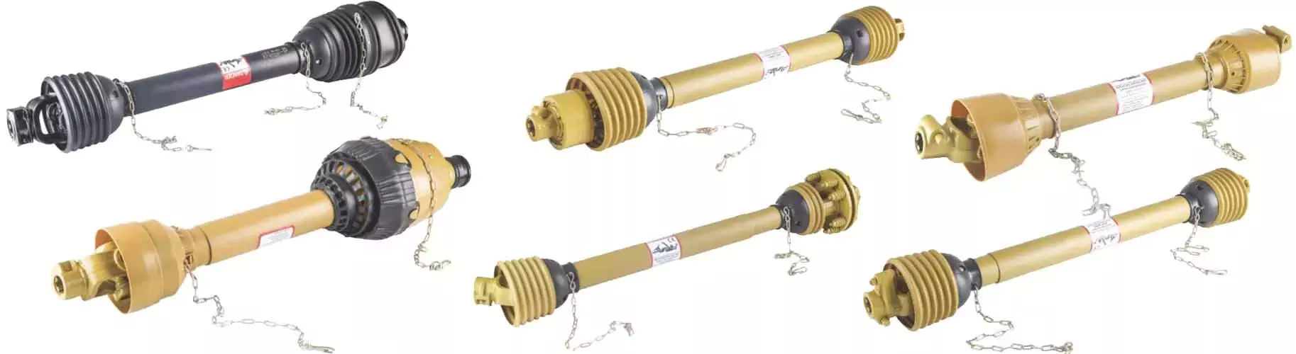
Shaft Collar

IID shaft guard

The IID shaft guard is a safety device used to protect PTO powered machinery from the possibility of separating while in use. The shaft, which is a telescoping shaft, is attached to the PTO stub on tractors. The telescopic feature is convenient when moving across uneven ground. However, this type of shaft can cause serious injury if it separates while in use.
The IID shaft guard can prevent these injuries by completely covering the shaft. The guard is made of metal or plastic and rotates along with the shaft. A person can react in less than five tenths of a second, making the IID shaft guard an important part of PTO safety.
PTO shafts rotate at speeds as high as 540 rpm, which is very fast. A limb could be wrapped around the driveline shaft, causing a serious injury or death. Because of the speed of a PTO, it can be difficult for an individual to discern whether it is engaged or not and may not be aware of the danger.
An IID shaft guard should be fitted to every tractor PTO shaft. It should be tested and rotated regularly. It is also important to keep the tractor engine off when working around the PTO shaft. Using a drawbar to protect driveline components is also important. It will prevent stress on the driveline and reduce the possibility of separation.

Overrunning clutch

An overrunning clutch on a PTO shaft is a mechanism that allows the PTO shaft to rotate freely in one direction while restricting the speed of the implement being hauled behind the tractor. This clutch is also useful for preventing the speed of the implement from exceeding the speed of the tractor while slowing down. It comes in two basic configurations, one for a clockwise and the other for a counter-clockwise direction.
Another type of overrun clutch is used on tractors with a PTO driven bush hog. A bush hog has a flywheel and blades that drive the transmission through the PTO shaft. Without an overrunning clutch, these implements would freewheel while the tractor is driving and would potentially break the shaft.
A PTO overrunning clutch prevents power from backfeeding into the transmission, the part that transmits power to the rear wheels. Without an overrunning clutch, the tractor could backfeed power, causing an accident if the blade assembly hits an object. As such, it is essential to use the overrunning clutch to ensure that your tractor will be safe.
Shaft Collar

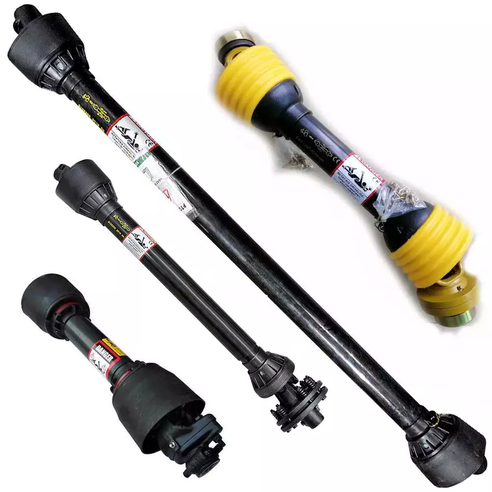
Direction of rotation

Despite its name, the direction of rotation of a PTO shaft can change if necessary. Most PTOs have a single-direction rotation, but you can often reverse the direction by installing a reverse PTO adapter. However, you should only use reverse PTOs when absolutely necessary.
A standard PTO rotation direction has been defined by the International Organization for Standardization (ISO). It is considered necessary to adhere to this standard, as improper rotation can cause damage to implements attached to a PTO. This standard helps farmers avoid problems such as ruined implements. While the direction of rotation of a PTO shaft is not always the same for all PTOs, there are some tractors that allow it to rotate both ways, while others have no restrictions.
The direction of rotation of a PTO shaft can be changed by using a hydraulic pump. Another way to connect a PTO is through a “sandwich” type split shaft unit. These units are mounted between the transmission and engine, and they usually receive drive directly from the engine shaft. They can also deliver complete engine power to a PTO. However, you must modify your vehicle’s driveline to install such a split-shaft unit.
China Hydraulic Pto Cast Iron Gearbox Kmt7001 1: 3.5     with high quality China Hydraulic Pto Cast Iron Gearbox Kmt7001 1: 3.5     with high quality
editor by CX 2023-04-07

China Professional Tractor Gearbox for Mower, Ratio 1: 1.92/1: 1.47, Agricultural Machines 540 Rpm with Hot selling

Product Description

Tractor Gearbox for Mower, Ratio 1: 1.92/1: 1.47, Agricultural Machines 540 Rpm

GEAR MATERIALS
20CrMnTi/20CrMnMo for your choice

CASTINGS MATERIALS
Gray cast iron HT250 according to standard GB/T 1348-2009 Ductile iron QT450-10 according to standard GB/T 1348-2009 Cast steel ZG310-570 according to standard GB/T 5613-2014

SHAFTS MATERIALS
40Cr,45#,20CrMnTi,20CrMnMo for your choice according to your request.

POWER To ensure the correct use of the product we recommand to pay attention to the specifications mentioned on our technical sheet.Consider also the input rotation speed,the power input and the transmission ratios.Where the rotation or other working conditions are different,please contact LongQuan technical department.

LUBRICATION
The reducer is usually supplied without lubricant.The recommended quantity of lubricant is indicated on our catalogue and the first replaced must be done after 50-60 hours of running,then replaced after 600-800 working hours. The emptying of the gearbox should be made immediately after the working,with the oil still hot,in order to avoid the deposition of sludge.Check frequently the oil level and top up the oil whenever necessary.


Related Products

Factory

Extensive use for agricultural machines
Guarantee: High precision, high wear resistance, low noise, smooth and steady, high strength

Our factory


Stiffness and Torsional Vibration of Spline-Couplings

In this paper, we describe some basic characteristics of spline-coupling and examine its torsional vibration behavior. We also explore the effect of spline misalignment on rotor-spline coupling. These results will assist in the design of improved spline-coupling systems for various applications. The results are presented in Table 1.
splineshaft

Stiffness of spline-coupling

The stiffness of a spline-coupling is a function of the meshing force between the splines in a rotor-spline coupling system and the static vibration displacement. The meshing force depends on the coupling parameters such as the transmitting torque and the spline thickness. It increases nonlinearly with the spline thickness.
A simplified spline-coupling model can be used to evaluate the load distribution of splines under vibration and transient loads. The axle spline sleeve is displaced a z-direction and a resistance moment T is applied to the outer face of the sleeve. This simple model can satisfy a wide range of engineering requirements but may suffer from complex loading conditions. Its asymmetric clearance may affect its engagement behavior and stress distribution patterns.
The results of the simulations show that the maximum vibration acceleration in both Figures 10 and 22 was 3.03 g/s. This results indicate that a misalignment in the circumferential direction increases the instantaneous impact. Asymmetry in the coupling geometry is also found in the meshing. The right-side spline’s teeth mesh tightly while those on the left side are misaligned.
Considering the spline-coupling geometry, a semi-analytical model is used to compute stiffness. This model is a simplified form of a classical spline-coupling model, with submatrices defining the shape and stiffness of the joint. As the design clearance is a known value, the stiffness of a spline-coupling system can be analyzed using the same formula.
The results of the simulations also show that the spline-coupling system can be modeled using MASTA, a high-level commercial CAE tool for transmission analysis. In this case, the spline segments were modeled as a series of spline segments with variable stiffness, which was calculated based on the initial gap between spline teeth. Then, the spline segments were modelled as a series of splines of increasing stiffness, accounting for different manufacturing variations. The resulting analysis of the spline-coupling geometry is compared to those of the finite-element approach.
Despite the high stiffness of a spline-coupling system, the contact status of the contact surfaces often changes. In addition, spline coupling affects the lateral vibration and deformation of the rotor. However, stiffness nonlinearity is not well studied in splined rotors because of the lack of a fully analytical model.
splineshaft

Characteristics of spline-coupling

The study of spline-coupling involves a number of design factors. These include weight, materials, and performance requirements. Weight is particularly important in the aeronautics field. Weight is often an issue for design engineers because materials have varying dimensional stability, weight, and durability. Additionally, space constraints and other configuration restrictions may require the use of spline-couplings in certain applications.
The main parameters to consider for any spline-coupling design are the maximum principal stress, the maldistribution factor, and the maximum tooth-bearing stress. The magnitude of each of these parameters must be smaller than or equal to the external spline diameter, in order to provide stability. The outer diameter of the spline must be at least four inches larger than the inner diameter of the spline.
Once the physical design is validated, the spline coupling knowledge base is created. This model is pre-programmed and stores the design parameter signals, including performance and manufacturing constraints. It then compares the parameter values to the design rule signals, and constructs a geometric representation of the spline coupling. A visual model is created from the input signals, and can be manipulated by changing different parameters and specifications.
The stiffness of a spline joint is another important parameter for determining the spline-coupling stiffness. The stiffness distribution of the spline joint affects the rotor’s lateral vibration and deformation. A finite element method is a useful technique for obtaining lateral stiffness of spline joints. This method involves many mesh refinements and requires a high computational cost.
The diameter of the spline-coupling must be large enough to transmit the torque. A spline with a larger diameter may have greater torque-transmitting capacity because it has a smaller circumference. However, the larger diameter of a spline is thinner than the shaft, and the latter may be more suitable if the torque is spread over a greater number of teeth.
Spline-couplings are classified according to their tooth profile along the axial and radial directions. The radial and axial tooth profiles affect the component’s behavior and wear damage. Splines with a crowned tooth profile are prone to angular misalignment. Typically, these spline-couplings are oversized to ensure durability and safety.

Stiffness of spline-coupling in torsional vibration analysis

This article presents a general framework for the study of torsional vibration caused by the stiffness of spline-couplings in aero-engines. It is based on a previous study on spline-couplings. It is characterized by the following three factors: bending stiffness, total flexibility, and tangential stiffness. The first criterion is the equivalent diameter of external and internal splines. Both the spline-coupling stiffness and the displacement of splines are evaluated by using the derivative of the total flexibility.
The stiffness of a spline joint can vary based on the distribution of load along the spline. Variables affecting the stiffness of spline joints include the torque level, tooth indexing errors, and misalignment. To explore the effects of these variables, an analytical formula is developed. The method is applicable for various kinds of spline joints, such as splines with multiple components.
Despite the difficulty of calculating spline-coupling stiffness, it is possible to model the contact between the teeth of the shaft and the hub using an analytical approach. This approach helps in determining key magnitudes of coupling operation such as contact peak pressures, reaction moments, and angular momentum. This approach allows for accurate results for spline-couplings and is suitable for both torsional vibration and structural vibration analysis.
The stiffness of spline-coupling is commonly assumed to be rigid in dynamic models. However, various dynamic phenomena associated with spline joints must be captured in high-fidelity drivetrain models. To accomplish this, a general analytical stiffness formulation is proposed based on a semi-analytical spline load distribution model. The resulting stiffness matrix contains radial and tilting stiffness values as well as torsional stiffness. The analysis is further simplified with the blockwise inversion method.
It is essential to consider the torsional vibration of a power transmission system before selecting the coupling. An accurate analysis of torsional vibration is crucial for coupling safety. This article also discusses case studies of spline shaft wear and torsionally-induced failures. The discussion will conclude with the development of a robust and efficient method to simulate these problems in real-life scenarios.
splineshaft

Effect of spline misalignment on rotor-spline coupling

In this study, the effect of spline misalignment in rotor-spline coupling is investigated. The stability boundary and mechanism of rotor instability are analyzed. We find that the meshing force of a misaligned spline coupling increases nonlinearly with spline thickness. The results demonstrate that the misalignment is responsible for the instability of the rotor-spline coupling system.
An intentional spline misalignment is introduced to achieve an interference fit and zero backlash condition. This leads to uneven load distribution among the spline teeth. A further spline misalignment of 50um can result in rotor-spline coupling failure. The maximum tensile root stress shifted to the left under this condition.
Positive spline misalignment increases the gear mesh misalignment. Conversely, negative spline misalignment has no effect. The right-handed spline misalignment is opposite to the helix hand. The high contact area is moved from the center to the left side. In both cases, gear mesh is misaligned due to deflection and tilting of the gear under load.
This variation of the tooth surface is measured as the change in clearance in the transverse plain. The radial and axial clearance values are the same, while the difference between the two is less. In addition to the frictional force, the axial clearance of the splines is the same, which increases the gear mesh misalignment. Hence, the same procedure can be used to determine the frictional force of a rotor-spline coupling.
Gear mesh misalignment influences spline-rotor coupling performance. This misalignment changes the distribution of the gear mesh and alters contact and bending stresses. Therefore, it is essential to understand the effects of misalignment in spline couplings. Using a simplified system of helical gear pair, Hong et al. examined the load distribution along the tooth interface of the spline. This misalignment caused the flank contact pattern to change. The misaligned teeth exhibited deflection under load and developed a tilting moment on the gear.
The effect of spline misalignment in rotor-spline couplings is minimized by using a mechanism that reduces backlash. The mechanism comprises cooperably splined male and female members. One member is formed by two coaxially aligned splined segments with end surfaces shaped to engage in sliding relationship. The connecting device applies axial loads to these segments, causing them to rotate relative to one another.